Subtotal: ₹11,748.00
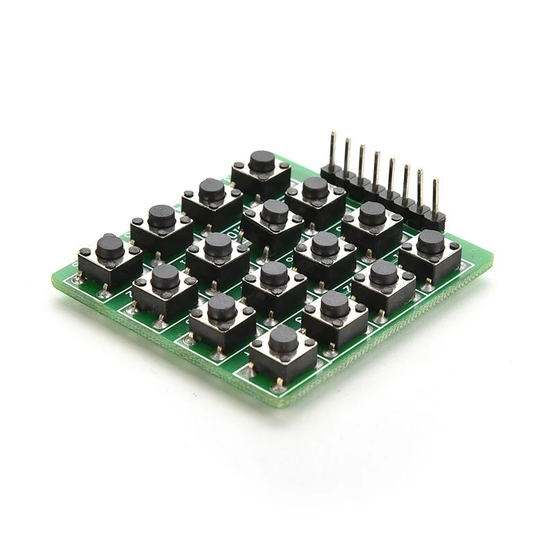
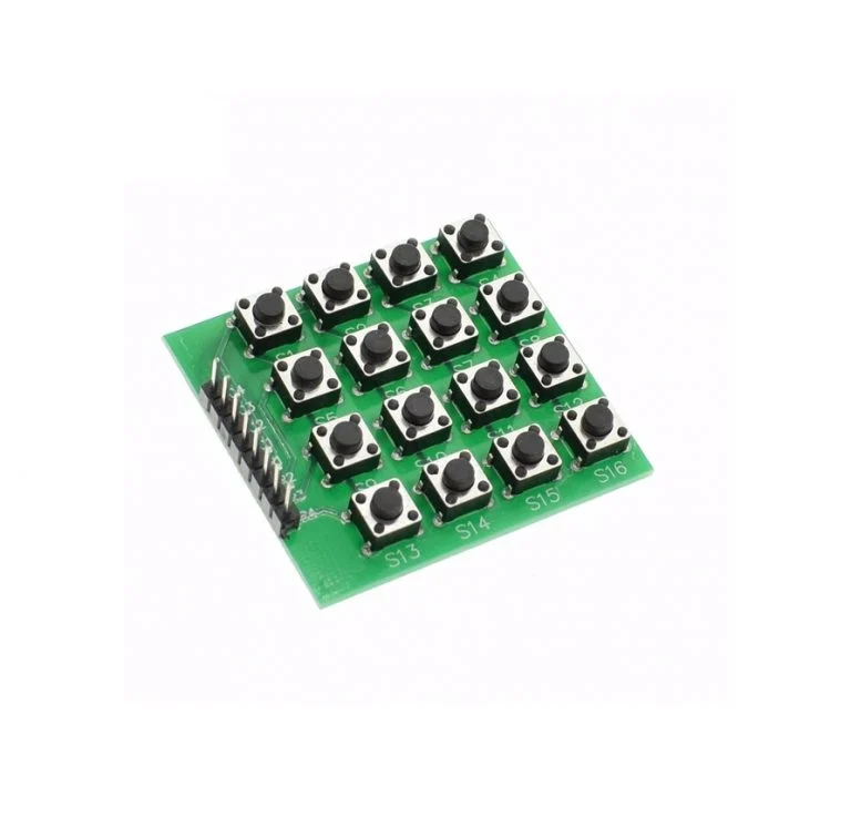
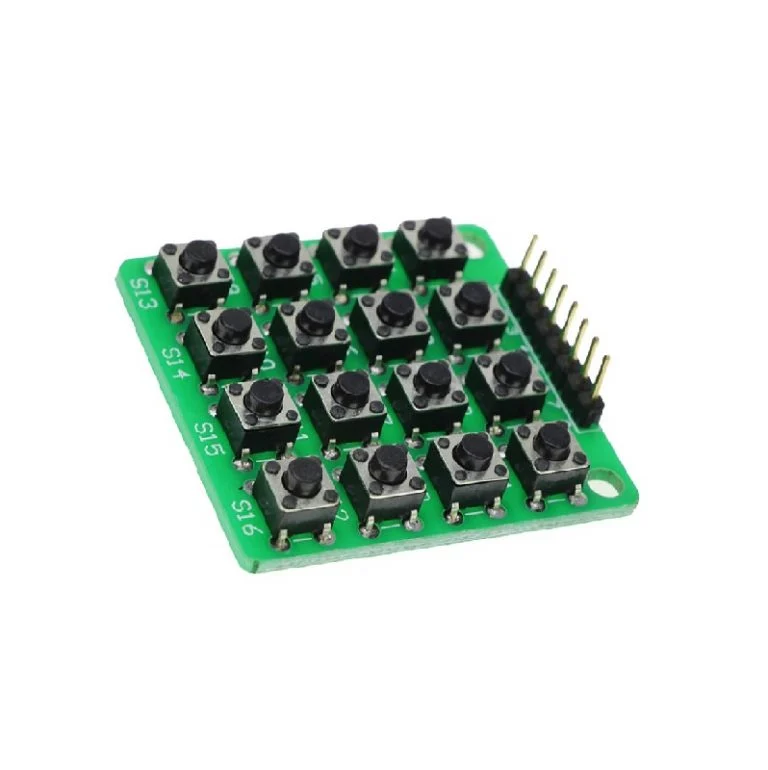
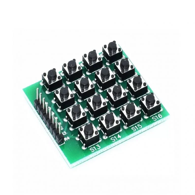
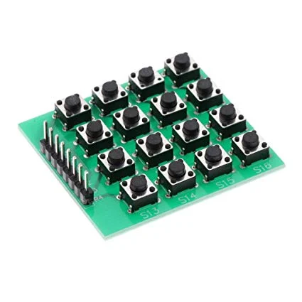
4×4 Matrix 16 Keypad Keyboard Module 16 Button MCU
- 4×4 Matrix Keyboard Module with 16 buttons
- Small in size and hence Save space
- More convenient to use
- Expanded development application modules for single chip
- With 16 keys and 8 pin
₹89.00 ₹149.00
The 4×4 matrix keypad serves as a common input device in various projects, offering 16 keys for input values. This non-encoded module features a parallel matrix arrangement, with the 16 keys interconnected through pins arranged as rows (labeled R1-R4) and columns (labeled L1-L4).
Comprising microswitch buttons, the keypad module includes four 3mm mounting holes (M3) for easy installation. Each PCB illustrates pin designations, with four pins allocated as ‘x’ coordinates and the remaining four as ‘y’ coordinates. Additionally, the module comes equipped with pre-soldered pin headers.
Here’s how it operates:
1. Begin by checking if any key is pressed. Apply power to the rows, setting them to a high level. Then, set all rows (R1-R4) to a low level and detect the status of the columns. A low status in any column indicates a pressed key within that column’s four keys. If all columns register as high, no key is pressed.
2. Once a pressed key is identified within a column, determine its exact location. By setting the rows individually to low status, the pressed row can be revealed, while the other rows remain high.
3. With the pressed row identified, proceed to test each column individually. The column registering as low intersects with the pressed row, pinpointing the exact key pressed at their intersection.
Package Includes:
1 x 4×4 Matrix 16 Keypad Keyboard Module 16 Button MCU
Based on 0 reviews
Only logged in customers who have purchased this product may leave a review.
 Raspberry Pi 4 Model B 8GB Starter Kit
  Waveshare GPIO Expander For Raspberry Pi Pico, 1x Raspberry Pi Standard 40PIN, 1x Pico 2?20PIN




There are no reviews yet.