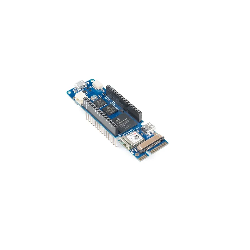
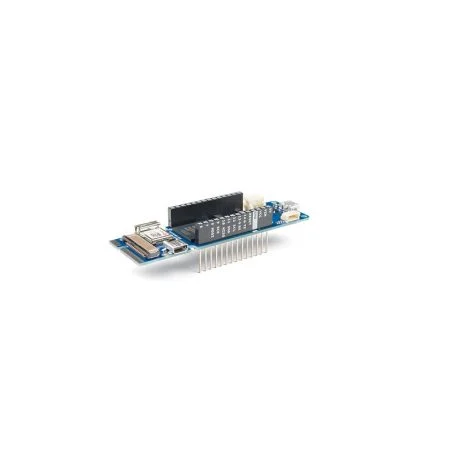
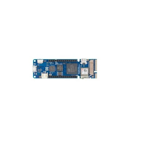
Arduino MKR Vidor 4000 ABX00022
Available on backorder
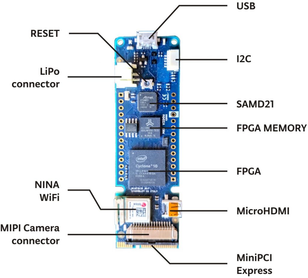
- FPGA: Intel® Cyclone® 10CL016
- PCI: Mini PCI Express port with programmable pins
- Camera Connector: MIPI camera connector
- Microcontroller: SAMD21 Cortex®-M0+ 32bit low power ARM MCU
- Radio module: u-Blox NINA-W102 (datasheet)
- Board Power Supply :(USB/VIN) 5V
- All pins are PWM pins
- MIPI camera connector
- Mini PCI Express port with programmable pins
- Full-Speed USB Device and embedded Host
₹6,499.00 ₹7,699.00
Available on backorder
The Arduino MKR Vidor 4000 brings Arduino’s ease of use to the work with the most powerful reprogrammable chips that exist: FPGAs. With Vidor, you can create a board where all pins are PWM signals controlling the speed of motors. You can capture sound in real-time and make a sound effect pedal for your guitar. It is possible to create a real-time computer reading sensor information and sending it to a state-of-the-art monitor or capture video and overlay sensor information on the image that will then later be sent over to a screen. You can connect to the Arduino IoT Cloud and control a complex laboratory machine running a large number of motors. You could even prototype your own processors inside the FPGA and have them work in parallel to the other microcontroller on the board. Vidor is a device that invites experimentation, precision, and high-speed computation.
The board comes with 8 MB of SRAM to support the FPGA operations on video and audio. The FPGA code is stored in a 2 MB QSPI Flash chip, of which 1 MB is allocated for user applications. It is possible to perform high-speed DSP operations for audio and video processing. Therefore, the Vidor includes a Micro HDMI connector for audio and video output and a MIPI camera connector for video input. All of the board’s pins are driven both by SAMD21 and FPGA while respecting the MKR family format.
Useful Steps:
- Open the Arduino IDE. Go to Tools->Boards->Boards Manager. Search and install “arduino SAMD boards”.
- Go to Tools->Manage Libraries. Search and install “WiFiNINA ver. 1.3.0” library.
- Go to File->Examples->WiFiNINA->Scan Networks. Select correct COM port. Compile and upload the program. Check the output in Serial Monitor.
Specification:
| Digital I/O Pins | 8 |
|---|---|
| PWM Digital I/O Pins | 13 |
| Clock Speed | 32.768 kHz (RTC), 48 MHz |
| Flash Memory | 256 KB (internal) |
| SRAM | 32 KB |
| DC Current per I/O Pin (mA) | 7 |
| Dimensions in mm (LxWxH) | 83x25x2 |
| Weight (gm) | 43 |
| Shipping Weight | 0.046 kg |
| Shipping Dimensions | 11.5 × 6 × 2.5 cm |
Features:
- All pins are PWM pins
- MIPI camera connector
- Mini PCI Express port with programmable pins
- Full-Speed USB Device and embedded Host
FPGA Block Specifications:
- FPGA: Intel® Cyclone® 10CL016
- PCI: Mini PCI Express port with programmable pins
- Camera Connector: MIPI camera connector
- Circuit Operating Voltage: 3.3V
- Digital I/O Pins: 22 headers + 25 Mini PCI Express
- PWM Pins: All Pins
- UART: Up to 7 (depends on FPGA configuration)
- SPI: Up to 7 (depends on FPGA configuration)
- I2C: Up to 7 (depends on FPGA configuration)
- Analog Input Pins: n/a
- Analog Output Pins: n/a
- External Interrupts: n/a
- DC Current per I/O Pin:4 or 8 mA
- Flash Memory:2 MB
- SDRAM: 8 MB
- EEPROM:n/a
- Clock Speed:48 MHz – up to 200 MHz
- Video Output: Micro HDMI
Package Includes:
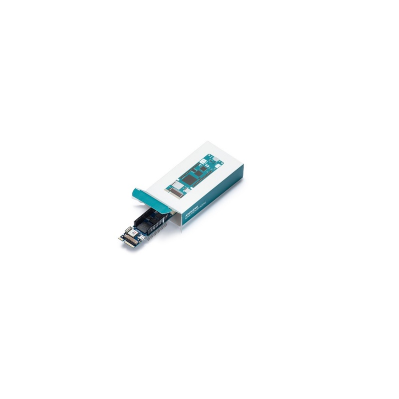
1 x Arduino MKR Vidor 4000 ABX00022
Based on 0 reviews
Only logged in customers who have purchased this product may leave a review.


There are no reviews yet.