
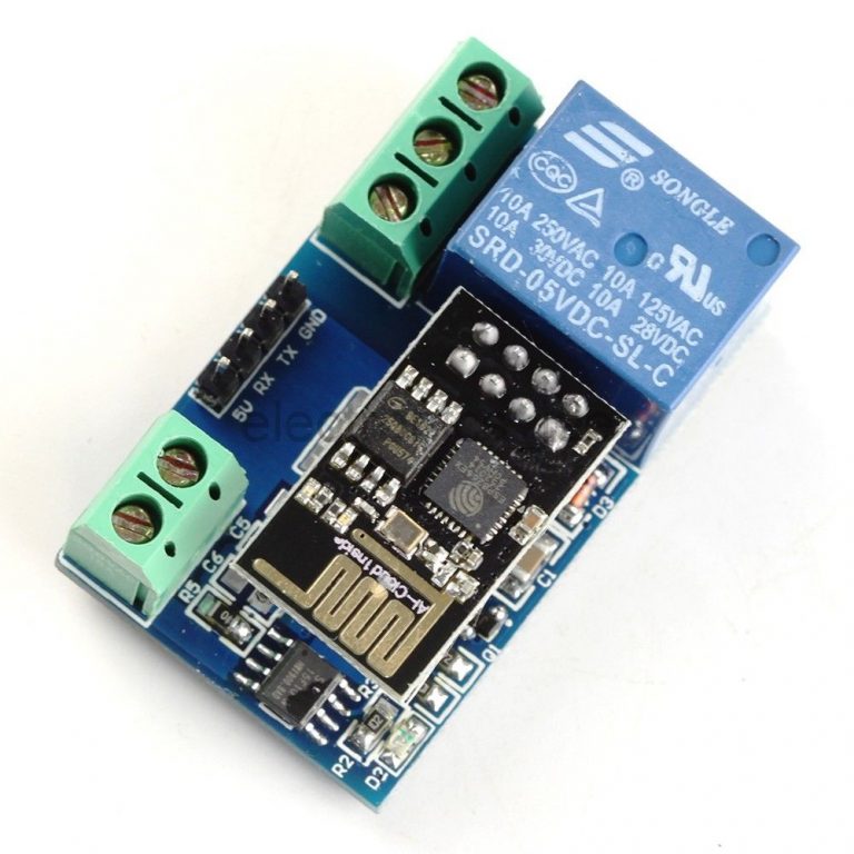


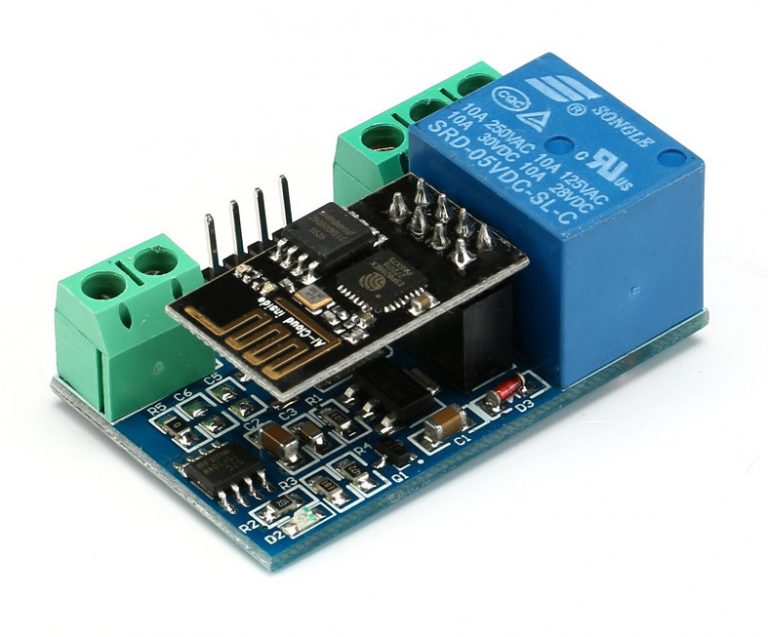
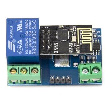
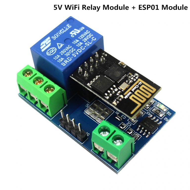
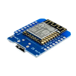
ESP8266 WiFi 5V 1 Channel Relay Module
Out of stock
- Onboard Module: ESP8266 wifi module; in AP mode it can connect with 5 Clients at the same time
- Operating Way: cellphone carried on wifi module; cellphone and wifi module carried on the same router, and use the APP to control relay
- Transmission Distance : 400m (max)
- Relay : 5V,10A/250V AC 10A/30V DC
- Baud Rate: 9600.
- Diode effusion protection;
- Short response time
₹460.00 ₹560.00
Out of stock
The ESP8266 WiFi 5V 1 Channel Relay Module is equipped with an ESP8266 WiFi module and microcontrollers, allowing wireless control of the relay within the LAN using serial instructions sent via a mobile phone app. The onboard relay supports 5V, 10A / 250V AC and 10A / 30V DC, with a lifespan of up to 10 million continuous pulls, along with diode flow protection and a short response time.
How to use:
1. The onboard ESP8266 WiFi module offers three operating modes: STA (client), AP (hotspot), STA + AP (client + hotspot). Select the corresponding mode based on the module’s operation.
2. To configure the WiFi module, use serial debugging software on a computer along with a USB to TTL module to send AT commands. Connect the USB to TTL module’s RX, TX, and GND pins to the corresponding pins on the module, and connect the IN +, IN -, and GND pins to a 5V power supply.
General Info:
- Onboard ESP8266 WIFI module, AP mode can be connected at the same time 5 client
- The module has two ways to work:
(i) mobile phone directly mounted on the WIFI module;
(ii) mobile phone and WIFI module also carried on the router.
Transmission distance:
- Open environment, the mobile phone mounted on the WIFI module when the maximum transmission distance of 400m.
- When the WiFI module and mobile phone at the same time carried on the router when the transmission distance according to the router’s signal weakly;
Board function description:
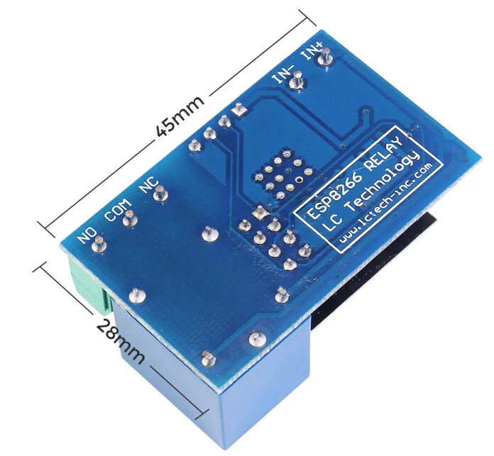
IN +, IN-: 5V power input;
TX, RX, GND: Serial debug pin;
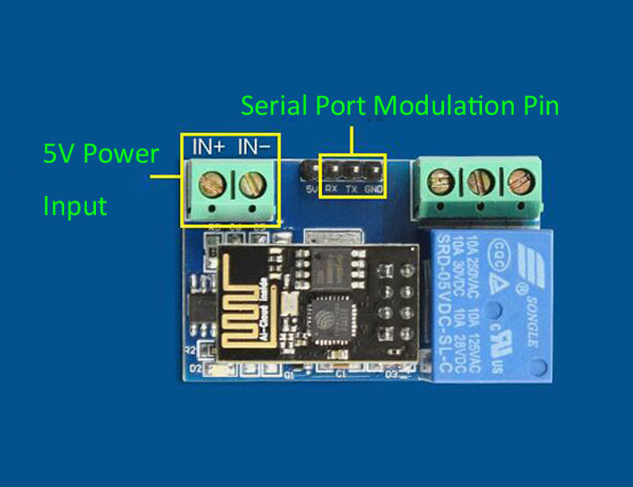
Onboard the ESP8266 WIFI module has three work modes: STA (client), AP (hot), the STA + Ap( hot +client), according to the workings of a module to the corresponding choice of WIFI module working mode. Module need before use serial debugging software and USB to TTL module send serial command was carried out on the WIFI module configuration (don’t power outages after configuration is complete, as some of the parameters of WIFI module cannot be saved when the power is cut off), mobile phone and WIFI module after establishing a network connection can use the phone APP control relay.
Control Commands:
When cell phone equipped with WiFi module sends commands in the following order:
(The default baud rate 115200)
- AT+CWMODE=2, namely AP mode is selected.
- AT+RST, reset.
- AT+CIPMUX=1, open multiple connections.
- AT+CIPSERVER=1,8080, configure the TCP server, set the port.
- AT+CIOBAUD=9600 set the baud rate to 9600. (working in relays to control the baud rate 9600).
- AT+CIFSR to view the AP mode IP address, such as the APIP, “192.168.4.1”.
- Cell phone WIFI signal connection name starts with AI-THINKER or ESP8266.
- In the “TCP connection” address and port into the APP, such as 192.168.4.1 and 8080.
- Click on the grey box relays can be controlled.
Package Includes:
1 x ESP8266 WiFi 5V 1-Channel Relay Module
Based on 0 reviews
Only logged in customers who have purchased this product may leave a review.
Related products
-
IoT & Wireless, xBee Zigbee modules
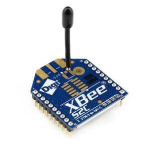
Zigbee XBee Pro S2C 802.15.4 Module 63mW 3Km+ 3.2dBi Antenna
- Supports binding and multicasting for home automation
- Mesh-network topology
- 2.4 GHz for worldwide deployment
- Common XBee footprint fits Parallax XBee Adapters and the Propeller Activity Board
- Firmware upgrades via UART, SPI or over the air
- TRANSCEIVER CHIPSET: SiliconLabs EM357 SoC
- DATA RATE: 250kbps Max
- RATED OUTDOOR/RF LINE-OF-SIGHT RANGE: Up to 2 mile (3200m)
SKU: n/a -
xBee Zigbee modules
Zigbee XBee Module S2C 802.15.4 2mW with Wire Antenna XB24CZ7WIT-004
- Integrated, Wire Antenna
- Interoperable with other ZigBee-compliant devices
- Programmable versions with onboard microprocessor enable custom ZigBee application development
- Supports binding and multicasting for easy integration into a home automation platform
- Data Rate: RF 250 Kbps, Serial up to 1 Mbps
- Range: Indoor 200 ft (60 m), Outdoor (LOS) 4000 ft (1200 m)
- Transmit Power: 3.1 mW (+5 dBm)
- Channels: 16 channels
SKU: n/a -
Development Boards
Mega +WiFi R3 Atmega2560+NodeMCU ESP8266 32Mb Memory USB-TTL CH340G Compatible For Arduino Mega
-11% Development Boards
Mega +WiFi R3 Atmega2560+NodeMCU ESP8266 32Mb Memory USB-TTL CH340G Compatible For Arduino Mega
- It is a customized version of the classic ARDUINO MEGA R3 board.
- Full integration of Atmel ATmega2560 microcontroller and ESP8266 Wi-Fi IC, with 32 Mb (megabits) of flash memory, and CH340G USB-TTL converter on a single board!
- All components can be set up to work together or independently.
SKU: n/a


There are no reviews yet.