-
×
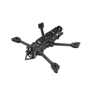 Assassin 5 inch 222mm Drone Racing frame Kit
1 × ₹3,299.00
Assassin 5 inch 222mm Drone Racing frame Kit
1 × ₹3,299.00 -
×
 400mm Trapezoidal 4 Start Lead Screw 8mm Thread 2mm Pitch Lead Screw with Copper Nut
1 × ₹289.00
400mm Trapezoidal 4 Start Lead Screw 8mm Thread 2mm Pitch Lead Screw with Copper Nut
1 × ₹289.00 -
×
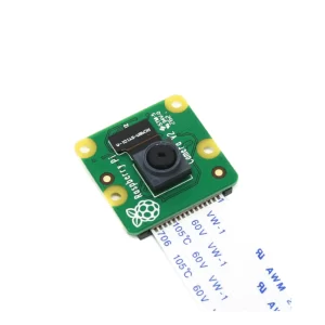 Official Raspberry Pi Camera V2
1 × ₹2,199.00
Official Raspberry Pi Camera V2
1 × ₹2,199.00 -
×
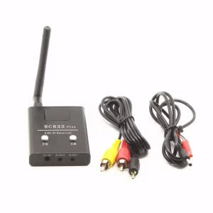 RC832 Plus 5.8G 48CH Wireless AV Receiver
1 × ₹2,389.00
RC832 Plus 5.8G 48CH Wireless AV Receiver
1 × ₹2,389.00 -
×
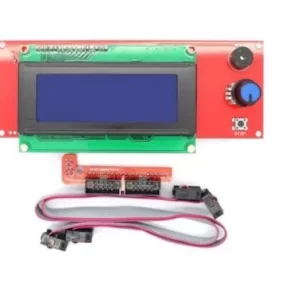 2004 LCD Display Rep-Rap Discount Smart Controller with Adapter
1 × ₹575.00
2004 LCD Display Rep-Rap Discount Smart Controller with Adapter
1 × ₹575.00 -
×
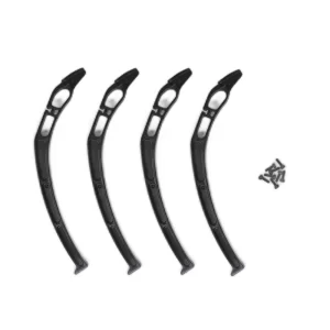 Ready to Sky Plastic Landing Gear for Quadcopter
1 × ₹219.00
Ready to Sky Plastic Landing Gear for Quadcopter
1 × ₹219.00 -
×
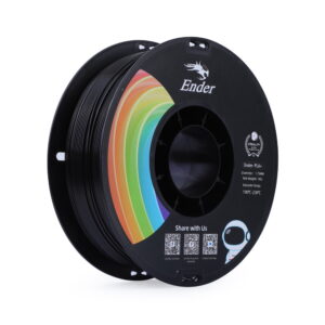 Creality Ender-PLA+ 3D Printing Filament 1.75mm (1kg – Black)
1 × ₹989.00
Creality Ender-PLA+ 3D Printing Filament 1.75mm (1kg – Black)
1 × ₹989.00 -
×
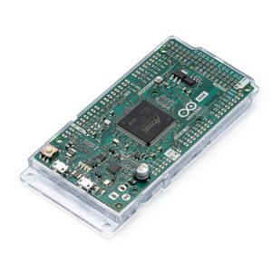 Arduino Due without Headers A000056
1 × ₹3,899.00
Arduino Due without Headers A000056
1 × ₹3,899.00 -
×
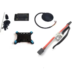 APM 2.8 Upgraded Flight Controller kit with GPS Module Combo Kit
1 × ₹8,276.00
APM 2.8 Upgraded Flight Controller kit with GPS Module Combo Kit
1 × ₹8,276.00 -
×
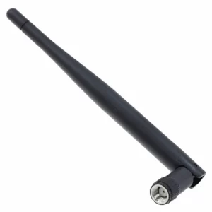 2.4GHz 3.2dBi RP-SMA female Omni Antenna for WiFi
1 × ₹219.00
2.4GHz 3.2dBi RP-SMA female Omni Antenna for WiFi
1 × ₹219.00 -
×
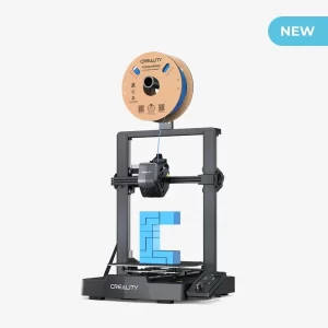 Creality Ender 3 V3 SE 3D Printer
1 × ₹23,899.00
Creality Ender 3 V3 SE 3D Printer
1 × ₹23,899.00 -
×
 500mm Trapezoidal 4 Start Lead Screw 8mm Thread 2mm Pitch Lead Screw with Copper Nut
1 × ₹432.00
500mm Trapezoidal 4 Start Lead Screw 8mm Thread 2mm Pitch Lead Screw with Copper Nut
1 × ₹432.00 -
×
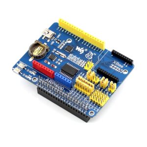 Waveshare Adapter Board for Arduino and Raspberry Pi
1 × ₹2,899.00
Waveshare Adapter Board for Arduino and Raspberry Pi
1 × ₹2,899.00 -
×
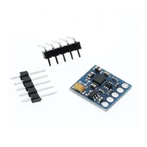 GY-271 QMC5883L 3-axis Electronic Compass Module Magnetic Field Sensor -(China Chip)
1 × ₹264.00
GY-271 QMC5883L 3-axis Electronic Compass Module Magnetic Field Sensor -(China Chip)
1 × ₹264.00 -
×
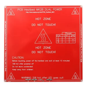 RepRap MK2B 3D printers Dual Power PCB Heat Bed With 18AWG Cable
1 × ₹948.00
RepRap MK2B 3D printers Dual Power PCB Heat Bed With 18AWG Cable
1 × ₹948.00 -
×
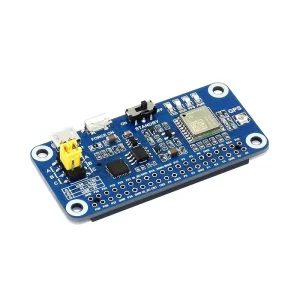 Waveshare L76X Multi-GNSS HAT for Raspberry Pi, GPS, BDS, QZSS
1 × ₹2,847.00
Waveshare L76X Multi-GNSS HAT for Raspberry Pi, GPS, BDS, QZSS
1 × ₹2,847.00 -
×
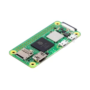 Raspberry Pi Zero 2 W
1 × ₹1,990.00
Raspberry Pi Zero 2 W
1 × ₹1,990.00 -
×
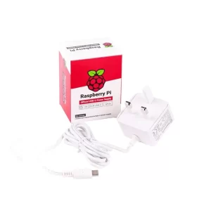 Raspberry Pi Accessory, Raspberry Pi 4 Model B Official PSU, USB-C, 5.1V, 3A, UK Plug, White
1 × ₹849.00
Raspberry Pi Accessory, Raspberry Pi 4 Model B Official PSU, USB-C, 5.1V, 3A, UK Plug, White
1 × ₹849.00 -
×
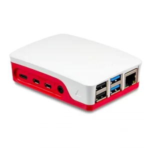 Official Raspberry Pi 4 Case-Red-White
1 × ₹449.00
Official Raspberry Pi 4 Case-Red-White
1 × ₹449.00
Subtotal: ₹56,930.00


There are no reviews yet.